DIY Drone/Quad Part 2 – Transmitter

In this part of the DIY drone/quad build, we are working on a transmitter. It would have been nice to have an R/C transmitter and receiver on hand, but I didn’t so I put one together from parts on the build sheet from Part 1 of these posts.
I mounted everything to a sheet of plexiglass, but you could use any easy to shape material. I plan to place all my components inside a 3d printed case, but that’s another post.
The parts we’ll use are (1)Arduino Nano, (1)nrf24 module, (1)Battery Holder Or Battery Pack, (2)joysticks, (1)3.3v regulator, and a handful of jumper wires, or you can solder everything together. I also held some things in place with zip ties while prototyping. Adding a switch is optional if you use jumper wires. My prototype on/off switch was a matter of plugging in the power wire to the Arduino VIN pin.
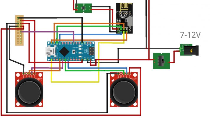
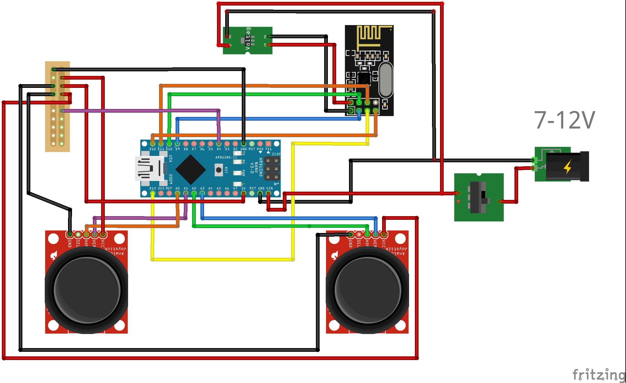
Here is the wiring diagram for the transmitter. We’ll upload and test code via the Arduino IDE later.

What are we doing?
- We are simply using an Arduino to interpret x and y axis inputs from each joystick. These will be our Throttle, Yaw, Pitch, and Roll.
- We are sending that signal via the nrf24 radio.
- The 3.3v regulator is required to supply steady 3.3 volts, and steady amps to the radio, which the Arduino 3v out pin cannot do on its own.
- A switch is used for on and off power.
- You might also notice I am adding a power wire to the pin D4. This is optional, I used it as a hardwired way to ensure the Auxiliary 1 channel signal was always set to high. This can have a switch, and probably should have a resistor added, or could be done arbitrarily in the code later. What it does in the end is turn on the stability, AKA ‘angle mode’ on the drone, making it much more flyable off the bat.
Need to step forward or backwards? Use the links for the build series below:
- This Overview – Part 1
- Build a transmitter/controller – Part 2
- Build a receiver – Part 3
- Build a flight controller to stabilize the quad/drone – Part 4
- Build a quad/drone frame – Part 5
- Program the transmitter, receiver, and flight controller with an Arduino IDE <- Software Using code called Multiwiiv – Part 6
- Calibrate the Motors with Multiwii code – Part 7
- Adjust settings and calibrate our gyro via Multiwii GUI AKA a graphical interface/software for your computer – Part 7

Leave a Reply