Real World Arduino Relay Use
Microcontrollers, like the Arduino, are great for manipulating lower voltage devices. On their own, they are limited in terms of the amount of voltage and current they can provide to devices. Many first Arduino projects involve motors, and LEDs, that require the use of transistors and additional external power sources.
To make full use of a microcontroller for home, garden, and hydroponic system manipulation, such as controlling lighting, pumps, and other AC devices, relays(buy one) need to be used.
If we had a legal team, they’d probably want us to cover our ass against stupidity. So here it is:
Warning! This is not a definitive guide to wiring AC applications, working with live electrical currents is dangerous, and can result in serious injuries, death, or damage to one’s property. Gardenisto and its authors are in No Way responsible for any injuries, damages, or deaths, caused by the use or misuse of the information contained on the Gardenisto website. Use of the information is at one’s own risk.
Now that we can carry on, what is a relay?
Very basically, it is an electrically operated switch, where the signal voltage source is completely isolated from the voltage being switched on or off.
For our example application of manipulating a 150 watt light from a wall outlet, we used a 120 volt 25 amp DC – AC solid state relay that will switch on when a voltage as low as 3 volts is applied. A suitable 10 amp ss relay can be purchased from suppliers like this one – Jameco
This works perfectly with the Arduino 5 volt output, on a digital pin. Not all microcontrollers will operate at 5 volts, some will operate at around 3.3v, so it is critical to understand the hardware you are using, and the interoperability of all your components.
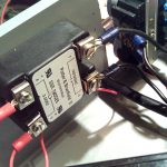
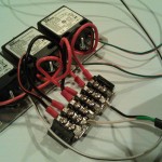
Unplugged, and unpowered, we wired the relay to an appropriate gauge Black AC wire, and finished the AC wiring to an AC wall receptacle mounted to our project enclosure. The receptacle was also selected based on application, and is rated to handle the amperage of our lighting.
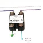
While the diagram for wiring a relay is quite simple, simple wiring mistakes can have serious consequences. So be careful, double check yourself, and never work with live electrical currents.
The remaining portion of the system requires the output of the microcontroller. A script turns the digital state of a pin HIGH. The high state toggles the relay, allowing current to flow through the relay.
The other end of the relays DC side is grounded, per the diagram.
Tags: ac controls, arduino, home automation, logic level dc input relay, relay Comments