LED Grow Lights
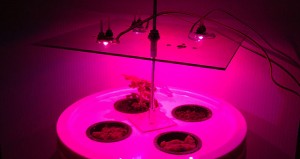
Build your own hydroponic LED growlight/system for germinating indoors. The system powers 1-4 3watt RGB LEDs on the Red and Blue channels.
The system easily fits on a bookshelf or desktop, and provides enough light for small sprouting plants to grow both thick foliage, and healthy stalks. Adjustable lighting height, prevents leggy growth.
Gardenisto takes no responsibility for the accuracy of the information posted, any injuries, death, or damages resultant from incorrectly attaching electrical devices.
Components
3x 1 watt RGB LEDS
3x Constant Current LED drivers
1x Sheet .125 Lexan
Nylon 4-40 Screw
4-40 washers and nuts
Large Project Enclosure or Conduit Box
AC Power cable (scrapped from old electronics)
12g 600v UL Cable (we actually used 18g)
24g UL Cable for dc wiring
¼” threaded rod and nuts
Mix pack of rubber grommets
Terminal Strip with a minimum 6 attachment strips
Terminal Jumper Strip
8 solderless terminal connectors
Drill w/Various Drill Bits
Skill Saw (or other saw for cutting plexi or lexan)
Basic Principles
LED Driver provides ample power for RGB LEDS
Red and Blue LEDs of the R-G-B LED will be powered, providing only usable light for germinating and growing young seedlings.
Pros
Compact Perfect for small desktop sized hydroponic germination units
Optionally Arduino controlled lighting
Low Power Consumption
Cons
Cost prohibitive versus off the shelf LED Grow lights with a standardized wall outlet
Power Consumption


 Trim Lexan to size of hydroponic bucket
Drill Center mounting post hole
Mark 4-40 size LED mounting holes
Mark center on lexan where LED will mount, this is where a cooling hole for the led will go
Drill mounting holes
Drill LED cooling holes
Mark and drill one additional hole, near each LED (this is where wires will pass to backside of lexan mounting plate)
Mark mounting holes for constant current LED drivers
Tap if enclosure is metal to prevent drill bit travel, then drill LED driver mounting holes
Mount LED drivers with 4-40 mounting screws and nuts
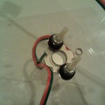
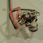
Solder the Red and Blue positive terminals to a red 24g wire approximately 3 feet in length
Solder the Red and Blue negative terminals to a black or green 24g wire approximately 3 feet in length
Repeat soldering for each LED on the system
Mount the LEDs to the Lexan mounting plate with Nylon 4-40 screws.
For a secure fit, place a rubber grommet on the backside of the mounting plate, sandwich the grommet with a washer and secure with a nut. Compression of the grommet will ensure a tight fit.
Run wires out of the way of the LEDs through the cable hole
Crimp terminal connectors to the Live and Neutral of the AC power cord
Cut and strip the ends off of 3 6 inch lengths of (Live Color) 12g wire
Cut and strip the ends off of 3 6 inch lengths of (Neutral Color) 12g wire
Crimp terminal connectors to a single end of each 6 inch length of wire
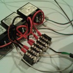
Cut the terminal jumper into two, three row lengths of the terminal strip.
Attach the LIVE end of the AC power cord to one set of the three terminals
Attach the NEUTRAL end of the AC power cord to the other set of three terminals
Attach the bare end of each 6 inch LIVE wire length to the constant currant LED driver in the appropriate screw terminal (Labelled “L”)
Attach the bare end of each 6 inch NEUTRAL wire length to the constant currant LED driver in the appropriate screw terminal (Labelled “N”)
Attach the terminal connector at the end of each 6 inch LIVE wire length to the LIVE terminal slots of the terminal strip.
Attach the terminal connector at the end of each 6 inch NEUTRAL wire length to the NEUTRAL terminal slots of the terminal strip.
Attach the LED wire leads to their respective LED driver screw terminals.
– Red wire to the screw terminals labeled “+”
– Black or Green wire to the screw terminals labeled “-”


Leave a Reply